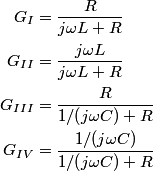
We can use phasor analysis to determine which of the circuits is a high-pass filter. A high-pass filter is defined as a circuit where the magnitude of the output signal and the magnitude of the input signal are identical when the input frequency goes to
 , and the magnitude of the output signal is , and the magnitude of the output signal is  when input frequency goes to when input frequency goes to  . .The voltage gain (which means the phasor input voltage divided by the phasor output voltage) for the four circuits are  For a high-pass filter, the magnitude of  should go to should go to  as as  and to and to  as as  . This is only true for . This is only true for  and and  . The other two circuits are low-pass filters. Therefore, answer (D) is correct. . The other two circuits are low-pass filters. Therefore, answer (D) is correct. |